Clement Poon

CP-2028 – Portfolio datasheet – Revised October 2026

CP-2028

Clement Poon

Electrical & Computer Engineering Student for Embedded, Hardware, and Digital-Design Roles, in a UT Austin Package

Seeking Summer 2027 internships & co-ops

CP-2028 pin configuration. Pins 1 to 7 list skills; pins 11 to 15 are links. CP-2028 ECE UT AUSTIN 1C/C++ 2VERILOG 3PYTHON 4KICAD 5ALTIUM 6LTSPICE 7FUSION360 8GND 16VCC RESUME15 EMAIL14 LINKEDIN13 GITHUB12 PROJECTS11 10EN 9NC (TOP VIEW)
Figure 1. CP-2028 pin configuration, DIP-16. Pins 11–15 are live links.

1Features

What I bring

  • Embedded C/C++ on Arm Cortex-M0+ (MSPM0) and ESP32; Python on Raspberry Pi
  • Custom power PCB design: 4S LiFePO₄ pack, BMS, buck regulation, MOSFET load switching
  • Digital design in Verilog on an Artix-7 FPGA, verified in Vivado simulation
  • 12 V automotive power distribution with relays and sensor-based shutdown
  • Bench-ready: oscilloscope, multimeter, bench supply, SMD & through-hole soldering, reflow
  • Two award-winning builds, including Best Overall Project out of 9 teams

2Applications

Roles I'm targeting

  • Summer 2027 internships
  • Co-op terms in 2027
  • Embedded systems & firmware
  • Hardware & PCB design
  • Digital logic & FPGA
  • Power electronics & systems

3Description

About me

I'm an Electrical and Computer Engineering student at UT Austin. Most of my experience is in embedded systems, hardware, and digital design: I designed a LiFePO₄ power board for a rocketry payload, co-founded an ESP32 smart planter that won Best Overall Project, and wrote a DOOM-style shooter from scratch for a Cortex-M0+ microcontroller.

I'm looking for an internship or co-op where I can apply those skills to real engineering problems.

Important notice: every project on this page is a real build. The part number is made up.

Device Information(1)
ProgramSchoolExpected graduationGPALocationAvailabilityLow-power modes
B.S. Electrical & Computer Engineering The University of Texas at Austin May 2028 3.68 / 4.00 Austin, TX Summer 2027 · 2027 co-ops Photography, car builds, running

(1) Full details in the résumé (PDF).

4

Projects

Things I've built

Selected builds across embedded firmware, power hardware, and digital logic. Each one lists the hardware, what I did, and where it got hard.

4.1

DOOM-Inspired Arcade Machine

Course project · Intro to Embedded Systems

Best project, in-class competition Demo video
  • C++
  • MSPM0G3507
  • Cortex-M0+
  • SPI
  • 12-bit DAC
  • 3D printing
Figure 4-1. Gameplay demo. Click to play.
Arcade machine block diagram An MSPM0G3507 microcontroller loads assets and audio from an SD card over SPI, drives an ST7735 TFT over SPI, reads player inputs, and streams double-buffered audio to a 12-bit DAC that feeds an amplifier and speaker. A 5 V external battery powers the system inside a 3D-printed cabinet. 3D-PRINTED CABINET 5 V battery external SD card assets · audio ST7735 TFT display MSPM0G3507 Cortex-M0+ · 80 MHz raycasting renderer depth-sorted sprites buf A buf B Player inputs controls 12-bit DAC Amplifier Speaker 5 V SPI SPI power data
Figure 4-2. Block diagram. Audio is double-buffered: one buffer fills from the SD card while the other streams to the DAC.

A first-person shooter written from scratch in C++ for a 32-bit microcontroller, built into a 3D-printed arcade cabinet.

Key specifications
MCUTI MSPM0G3507, Arm Cortex-M0+ at 80 MHz
GraphicsRaycasting 3D renderer with depth-sorted animated sprites on an ST7735 TFT (SPI)
AudioDouble-buffered streaming from an SD card to a 12-bit DAC, driving a separate amplifier
EnclosureSelf-designed 3D-printed cabinet with a speaker enclosure, powered by a 5 V external battery

What I did

  • Wrote the rendering system: a raycaster plus depth-sorted, animated sprites.
  • Built the audio engine: one buffer fills from the SD card while the other plays, getting enough throughput out of the 80 MHz clock for glitch-free music, footsteps, and effects.
  • Integrated the TFT and SD-card asset loading over SPI, and designed and printed the cabinet.
4.2

Payload Power & Sensor Board

Longhorn Rocketry Association · Payload subteam · Aug 2025 – present

  • PCB design
  • LiFePO₄ + BMS
  • Buck converter
  • MOSFETs
  • I²C / SPI
  • Python
Payload power and sensing architecture A 4S LiFePO4 pack feeds a BMS. The battery rail powers a buck converter that supplies 5 V to a Raspberry Pi 4, and MOSFET switches that drive nitinol actuators. The Pi controls the MOSFETs with a low-current GPIO signal, reads an IMU and a thermocouple over I2C/SPI, and runs a Python data logger. 4S LiFePO₄ pack 12.8 V nominal BMS battery management Buck converter TPS62933 · 5 V out MOSFET switches on the custom PCB Nitinol actuators high-current load BerryIMU motion · alt. Thermocouple temperature Raspberry Pi 4 payload computer Python data logger launch → recovery VBAT 5 V I²C / SPI GPIO power data control
Figure 4-3. Payload power and sensing architecture (simplified).

Power and sensing hardware for the rocket's payload: a custom board that keeps the payload's Raspberry Pi on regulated 5 V while switching high-current actuators straight off the battery.

Key specifications
SourceFour LiFePO₄ cells (4S, 12.8 V nominal) with a BMS
RegulationBuck converter supplying regulated 5 V to a Raspberry Pi 4
Load switchingNitinol actuators powered from the battery through on-board MOSFETs
SensingBerryIMU and thermocouple over I²C/SPI, logged in Python

What I did

  • Designed the power schematic and PCB: battery pack, BMS, and buck converter for stable 5 V through flight.
  • Routed actuator power through MOSFETs on the board so the Pi's GPIO only sends a low-current control signal.
  • Interfaced the IMU and thermocouple and wrote the Python logger that records motion, altitude, and temperature from launch through landing and recovery.
4.3

Vehicle Power, Electrical & Audio System

Personal build · my Toyota Corolla Hybrid · ongoing

  • 12 V distribution
  • Relays
  • Buck converters
  • ESP32
  • BLE
  • Sensors
  • Harnessing
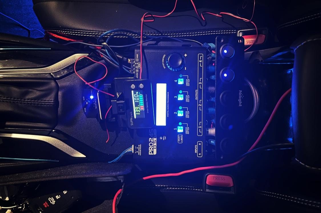
Car center console at night with a digital audio processor, a battery monitor reading 13.9 volts, and a panel of lit switches
Figure 4-4. Center console: DSP, battery monitor, and the 5-switch cut-off panel.

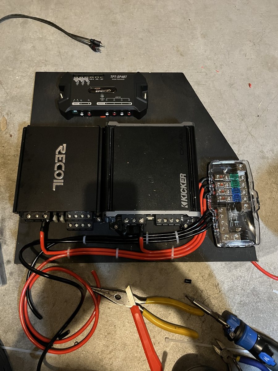
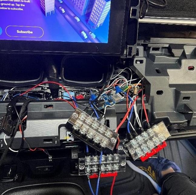
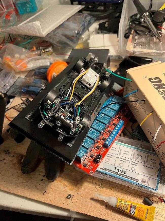
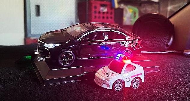
A long-running build on my own car: a 12-speaker audio system, a dashboard model car that mirrors the real car's lights, and the 12 V power and protection to run it all.

Key specifications
Audio12 speakers on 3 amplifiers, with a DSP in the center console
Power4 AWG feed through the firewall to distribution blocks; peaks near 70 A (≈900 W)
Control8 relays, buck converters (12 V → 5 V) for the microcontrollers, and a BLE link from the trunk amp rack to a front-mounted controller that drives the displays
ProtectionTemperature, humidity, vibration, and sound sensors; automatic power-off on overheating, high humidity, or sudden movement
StatusOngoing: rebuilding the ESP32 relay controller after a board failure

What I did

  • Planned the power distribution and wired the system myself, from the 4 AWG battery feed to the relay boards.
  • Wired a dashboard model car to mirror the real car's turn signals, headlights, and brake lights in real time through 8 relays.
  • Tracked down and fixed battery drain, speaker noise, and parasitic draw (below).
Engineering notes: problems & fixes
Problems found during the build
SymptomRoot causeFix
Battery drained over timeThe hybrid's DC-DC converter supplies only ~80 A to the 12 V battery, and the audio system peaks near 70 A, leaving little headroomSwitched to a more efficient Class D amplifier and opened up the woofer baffles to use the full door cavity
Noise through the speakersRCA signal cables ran too close to the power wiresPower runs down the right door sills and RCAs down the left, isolating the two
Parasitic draw with the car offDC-DC converters and relays drew power continuouslyAdded 5 center-console switches to cut power to individual components
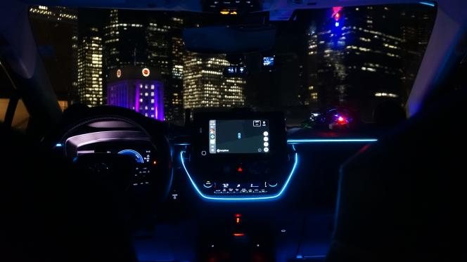
Car interior at night with blue ambient lighting and a city skyline through the windshield
Figure 4-5. Finished interior at night.
4.4

Mintality Smart Planter

Texas Convergent · IoT subteam · Co-founder & hardware lead · Jan 2026 – present

Best Overall Project, 9 teams Project slides
  • ESP32
  • C++
  • Firebase RTDB
  • Wi-Fi
  • DRV8833
  • ST7735
Mintality block diagram A capacitive soil-moisture sensor feeds the ESP32's ADC. The ESP32 drives a TFT display over SPI, sends timed pulses to a DRV8833 motor driver that runs the water pump, and syncs over Wi-Fi with a Firebase Realtime Database connected to the habit-tracking app. Soil moisture capacitive ESP32 C++ firmware power mgmt: CPU-freq scaling + driver sleep ST7735 TFT 3 animated faces Firebase RTDB status · commands Habit app goals → watering DRV8833 motor driver Water pump waters the plant ADC SPI Wi-Fi sync pulses
Figure 4-6. Mintality block diagram.

An ESP32 smart planter that pairs with a habit-tracking app: complete your goals and it waters a real plant.

Key specifications
MCUESP32 (Wi-Fi) running C++ firmware
I/OCapacitive soil-moisture sensor, pump on a DRV8833 driver with timed pulses, ST7735 TFT
CloudFirebase Realtime Database for plant status and remote watering commands
PowerCPU-frequency scaling and motor-driver sleep

What I did

  • Co-founded the project and led the hardware design.
  • Wrote the firmware for sensing, timed watering, and a display that shows plant health as one of three animated faces.
  • Integrated Firebase over Wi-Fi to keep the app and planter in sync, and tuned CPU frequency and driver sleep to cut power use.
4.5

FPGA Taiko Drumming Game

Digital design project · Basys3 board

  • Verilog
  • Artix-7
  • FSM design
  • Vivado
  • Simulation
FPGA drumming game, simplified functional block diagram Sixteen switches set the note pattern for a 12-state controller FSM on an Artix-7 FPGA. Button presses go to the scroll and scoring logic, which runs on a second clock domain derived from the 100 MHz board clock and drives the seven-segment display. SW[15:0] note pattern Buttons drum hits 100 MHz board clock ARTIX-7 FPGA · BASYS3 Controller FSM 12 states Scroll & scoring 3 speeds · hit check · score Clock domains board clock → scroll clock 7-segment display state scroll clk
Figure 4-7. Simplified functional view. The full design has 10 Verilog modules.

A Taiko-style rhythm game in Verilog: set a 16-step note pattern on the switches, then hit the buttons in time as it scrolls across the seven-segment display.

Key specifications
BoardBasys3, Artix-7 FPGA
Design10 Verilog modules, 12-state FSM, two clock domains
Gameplay16-switch note pattern, 3 scroll speeds, final score calculation
VerificationVivado simulation before deploying to hardware

What I did

  • Built the game from 10 modules around a 12-state FSM spanning two clock domains.
  • Debugged module interfaces, latch inference, and timing in Vivado simulation before anything went to the board.
4.6

Compliant Wheel for NASA's VIPER Rover

NASA SEES internship · VIPER team · Jun – Dec 2024

  • FEA
  • Fusion 360
  • Materials selection
  • 3D printing
  • Team lead
Concept sketch of a compliant unibody wheel Illustration of a one-piece wheel whose spokes are curved leaf springs between the hub and the rim, with tread on the outside. Unibody, 3D-printable Built-in leaf springs Rim with tread 6 geometries × 3 materials titanium selected
Figure 4-8. Concept sketch of a compliant unibody wheel (illustrative, not the final geometry).

Summer research with NASA SEES: a 3D-printable compliant wheel with built-in leaf springs for NASA's VIPER lunar rover, aimed at better shock absorption and simpler manufacturing for extreme polar terrain.

Key specifications
RoleTeam lead, 6-person team
AnalysisFEA in Autodesk Fusion 360 across 6 wheel geometries and 3 materials
MaterialsAluminum, steel, and titanium; titanium gave the best balance of flexibility and safety factor
OutputResearch poster at AGU24, the American Geophysical Union's 2024 meeting

What I did

  • Led the team's wheel design and the FEA study comparing geometries and materials.
  • Worked with VIPER engineers to refine recommendations for wheel traction and durability.

4.7 Earlier builds

  • Fingerprint-verified ignition (Secured Drive). A fingerprint reader on the ignition button verifies the driver before the car starts, designed to pair with a phone for remote start and per-driver presets, running off the car's 12 V system.
  • Sound-reactive lighting. Fed a computer's audio output into an Arduino that lights LEDs by frequency band, using per-band averages and transient detection to compensate for changes in volume.
5

Experience

Where I've worked
  1. Current
    Sep 2026 – Present

    STEAMWorks · Austin, TX

    LEGO Robotics Instructor (part-time)

    • Co-teach after-school robotics classes for 70+ K–5 students, guiding hands-on engineering and coding with LEGO kits.
    • Support instructors across 5 weekly classes at 12 Austin elementary schools, handling setup and student instruction.
  2. Current
    Jan 2026 – Present

    Texas Convergent, IoT Subteam · Austin, TX

    Co-Founder & Hardware Lead, Mintality

    • Won Best Overall Project among 9 teams with an ESP32 smart planter tied to a habit-tracking app.
    • Led hardware and wrote the C++ firmware: soil sensing, pump control, TFT display, and Firebase sync.
    See the project →
  3. Current
    Aug 2025 – Present

    Longhorn Rocketry Association · Austin, TX

    Electronics Member, Payload Subteam

    • Designed the payload's LiFePO₄ power PCB: BMS, buck regulation to 5 V, and MOSFET actuator switching.
    • Interfaced IMU and thermocouple sensors and wrote the Python flight data logger.
    See the project →
  4. Completed
    Jun 2024 – Dec 2024

    NASA SEES (STEM Enhancement in Earth Science) · Austin, TX

    VIPER Team Summer Research Intern

    • Led a 6-person team designing a 3D-printable compliant wheel for NASA's VIPER lunar rover.
    • Ran Fusion 360 FEA across 6 geometries and 3 materials and presented the results at AGU24 with input from VIPER engineers.
    See the project →
6

Skills

Tools and where I've used them
Skills, tools, and where each was used
AreaSkillsWhere I used them
LanguagesC, C++, Python, Verilog, Arm assembly, Java, MATLABArcade machine (C++) · Rocketry board (Python) · Mintality (C++) · FPGA game (Verilog)
Embedded platformsArm Cortex-M0+ (MSPM0), ESP32, Raspberry Pi, FPGAsArcade machine · Rocketry board · Mintality · FPGA game
InterfacesSPI, I²C, Wi-Fi, BLE, Firebase Realtime DatabaseArcade machine (SPI) · Rocketry board (I²C/SPI) · Car system (BLE) · Mintality (Wi-Fi)
PCB & simulationPCB design, KiCad, Altium, LTspiceRocketry power board
PowerLiFePO₄ packs & BMS, buck converters, MOSFET switching, relays, 12 V distributionRocketry board · Car system
Digital designVerilog, Vivado, design verificationFPGA game
Mechanical & CADFusion 360 (certified), AutoCAD, FEA, 3D printingArcade cabinet · VIPER wheel
Lab & fabricationOscilloscope, multimeter, bench power supply, soldering & reflow, SMD & through-hole, crimping & harnessingCar system wiring & harnessing
ToolsGit, Linux, Adobe Suite—
7

Education

School and coursework

The University of Texas at Austin

B.S. Electrical and Computer Engineering · Cockrell School of Engineering

Expected
May 2028
GPA
3.68 / 4.00

Relevant coursework

8

Contact

Ways to reach me

Recruiting for Summer 2027 or a 2027 co-op? I'd like to hear about it.

Prefer to leave a message? Fill out a short form and it comes straight to my inbox.

Send me a message